Rigid cylinder contact with block: rigidCylinderContactBrick
Prepared by Philip Cardiff and Ivan Batistić
Tutorial Aims
- Demonstrate how to enforce a frictionless contact boundary condition with an analytically defined rigid surface;
- Demonstrate the use of a penalty approach for contact between a deformable solid and a prescribed rigid cylinder;
- Provide a simple starting point for adding similar analytical contact boundary conditions, for example contact with a rigid plane.
Case Overview
This case considers a 2-D plane strain elastic block in contact with an analytically defined rigid cylinder (Figure 1). The material is linear elastic steel, with Young's modulus \(E = 200\) GPa and Poisson's ratio \(\nu = 0.3\). Gravity is neglected. The problem is solved using the small strain assumption. The rigid cylinder is not part of the computational mesh. Instead, it is defined analytically as \((x - c_x)^2 + (y - c_y)^2 = r^2,\)
where \((c_x, c_y)\) is the current cylinder centre and \(r\) is the cylinder radius. The green cylinder in Figure 1 is shown only to visualise the analytical contact surface. The cylinder radius is \(r = 1\) m. The cylinder centre is prescribed using the table in constant/timeVsCylinderCentre: from \(t = 0\) s to \(t = 5\) s the cylinder moves vertically down into contact, from \(t = 5\) s to \(t = 10\) s it slides horizontally while maintaining the same indentation, and from \(t = 10\) s to \(t = 15\) s it moves vertically upward.
The rigidCylinderContact boundary condition checks each face on the contact patch. If the deformed face centre is inside the analytical cylinder, a radial contact traction is applied using a penalty relation proportional to the overlap distance. Faces outside the cylinder are treated as zero-traction faces. In this case, the penalty stiffness is \(1 \times 10^9\) Pa/m and the contact traction is under-relaxed with relaxFactor 0.1.
up
{
    type                rigidCylinderContact;
    cylinderRadius      1.0;
    cylinderCentre
    {
        "fileName|file" "$FOAM_CASE/constant/timeVsCylinderCentre";
        outOfBounds     clamp;
    }
    penaltyStiffness    1e9;
    relaxFactor         0.1;
    value               uniform (0 0 0);
}
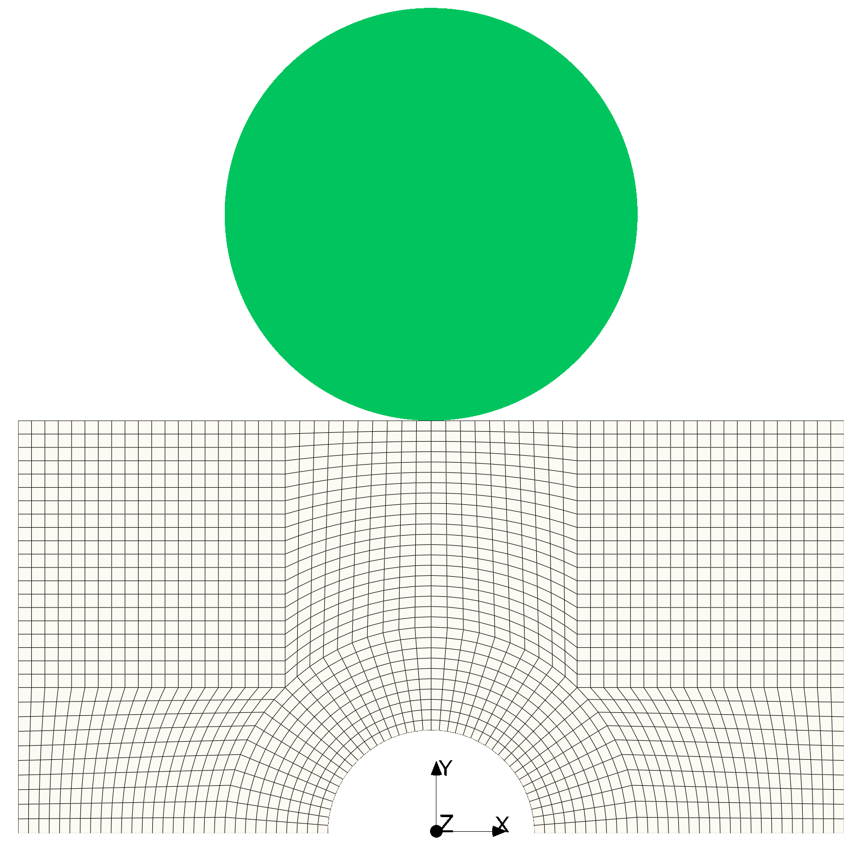 Figure 1: Computational mesh and analytically defined rigid cylinder
Expected Results
This case does not have an analytical solution for direct quantitative comparison. The expected response is qualitative: as the rigid cylinder moves down, a local indentation forms on the top surface of the block; as it slides to the right, the compressive stress field follows the contact region.
Figure 2 shows the deformed configuration and \(\sigma_{yy}\) stress field at \(t = 10\) s, where the cylinder has completed the horizontal sliding stage. The deformation is scaled by a factor of \(500\).
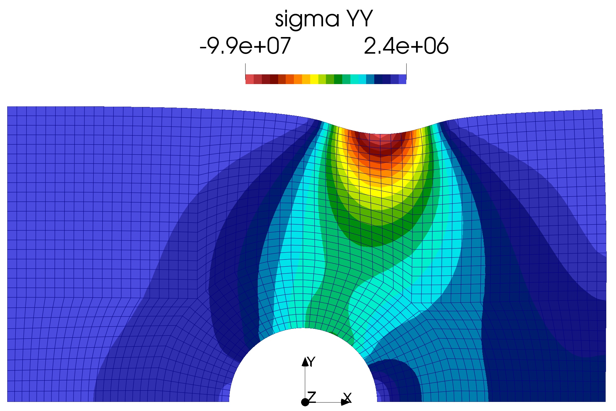
Figure 2: \(\sigma_{yy}\) stress distribution at \(t = 10\) s
Running the Case
The tutorial case is located at solids4foam/tutorials/solids/linearElasticity/rigidCylinderContactBrick.
The case can be run using the included Allrun script:
./Allrun
The script converts the case format if required, creates the mesh using blockMesh, and then runs the solids4Foam solver.