Tutorial: narrowTmember
Prepared by Philip Cardiff
Tutorial Aims
- Demonstrate how to perform a linear-static stress analysis of a 3-D engineering component in solids4foam;
- Compare the performance of three variants of the same tutorial case:
petscSnes, which uses thelinearGeometryTotalDisplacementsolid model with a PETSc SNES solution algorithm;segregated, which uses the same solid model with an implicit segregated solution algorithm; andunsCoupled, which uses the originalcoupledUnsLinearGeometryLinearElasticsolid model. - Show how to modify a case, which originally used the
coupledUnsLinearGeometryLinearElasticsolid model, to instead use thelinearGeometryTotalDisplacementsolid model with PETSc SNES.
Case Overview
This case comprises a narrow engineering component with a T cross-section (Figure 1). This case was proposed as a benchmark by Demirdzic et al., 1997, Benchmark solutions of some structural analysis problems using the finite-volume method and multigrid acceleration. Int J Numer Methods Eng. Due to symmetry, the solution domain consists of one-quarter of the component. A constant negative pressure of 1 MPa is applied to the lower surface, and the upper left surface is fully clamped (Figure 1). The Young's modulus is 210 GPa, and Poisson's ratio is 0.3. A radius \(R = 5\) mm hole is located at the expected stress concentration. Four separate systematically refined hexahedral meshes (624, 4992, 39 936, and 319 488 cells) are examined here, mimicking the meshes employed by Demirdzic et al.; the coarsest mesh is shown in Figure 2.
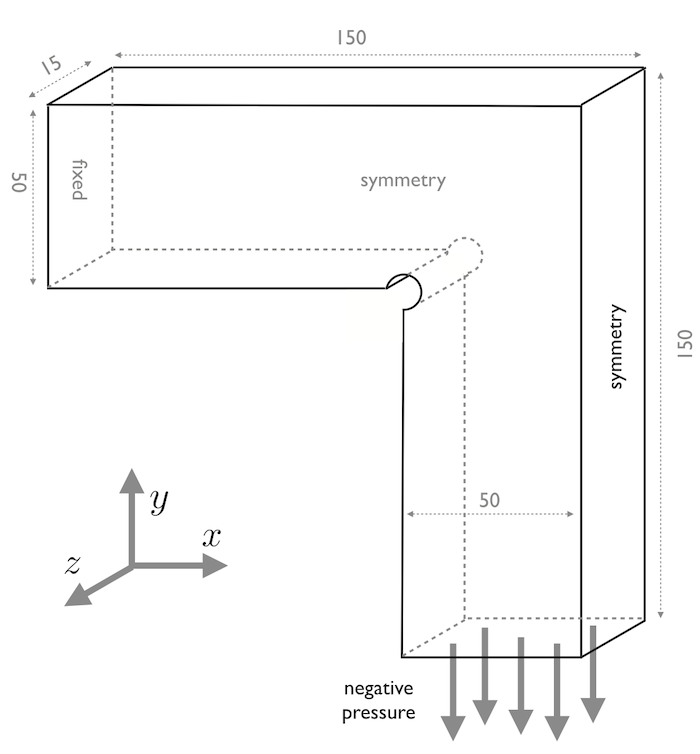
Figure 1 - Geometry and loading with dimensions in mm
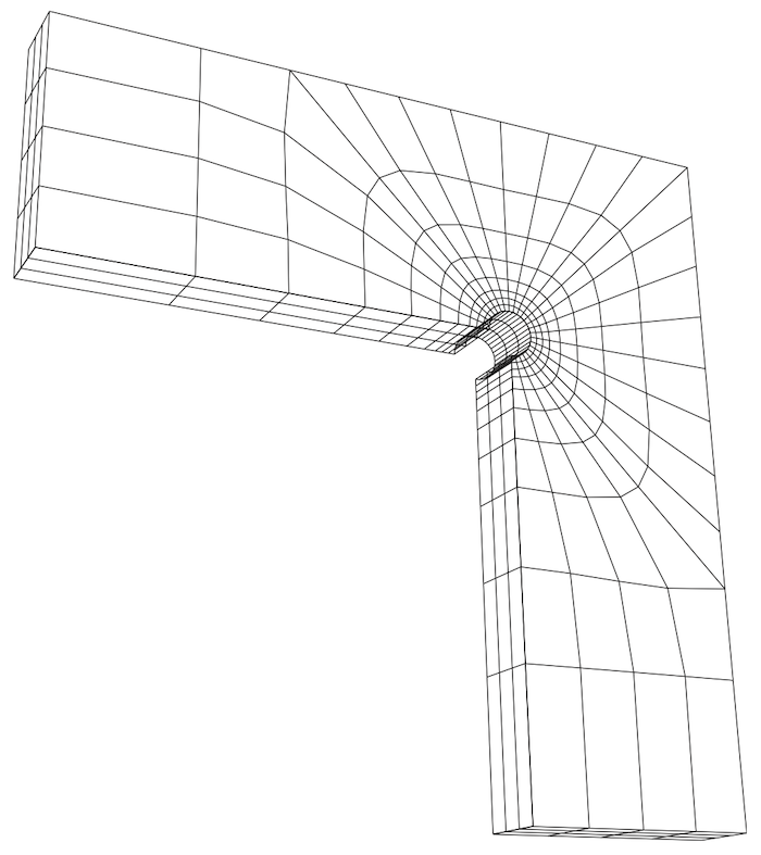
Figure 2 - Coarest hexahedral mesh (624 cells)
Running the Case
The tutorial case is located at solids4foam/tutorials/solids/linearElasticity/narrowTmember. The case can be run using the included Allrun script. Two variants are available:
./Allrun                # Defaults to the petscSnes variant
./Allrun segregated     # Segregated variant
./Allrun unsCoupled     # Original foam-extend-only variant
In both cases, the Allrun script simply creates the mesh using blockMesh and then runs the solids4foam solver.
The default petscSnes variant uses the linearGeometryTotalDisplacement solid model with PETSc SNES. The original unsCoupled variant is also provided through the .unsCoupled file suffixes, and uses the coupledUnsLinearGeometryLinearElastic solid model together with the original block* boundary conditions and coupled discretisation settings. The unsCoupled variant can currently only be run using solids4foam built on foam-extend.
The segregated variant uses the same linearGeometryTotalDisplacement solid model as petscSnes, but with solutionAlgorithm implicitSegregated; in constant/solidProperties. This variant is intended for comparison with the PETSc SNES path using the same geometry and boundary conditions.
The case can then be run as before, i.e. > blockMesh && solids4Foam.
Expected Results
Figure 3 shows the \(\sigma_{xx}\) and \(\sigma_yy\) stress distributions on the plane z = 0 m (symmetry plane) for the finest mesh. The predictions agree closely with the results of Demirdzic et al. Further comparisons can be found in Cardiff et al., 2016, A block-coupled Finite Volume methodology for linear elasticity and unstructured meshes, Comp. and Struct.
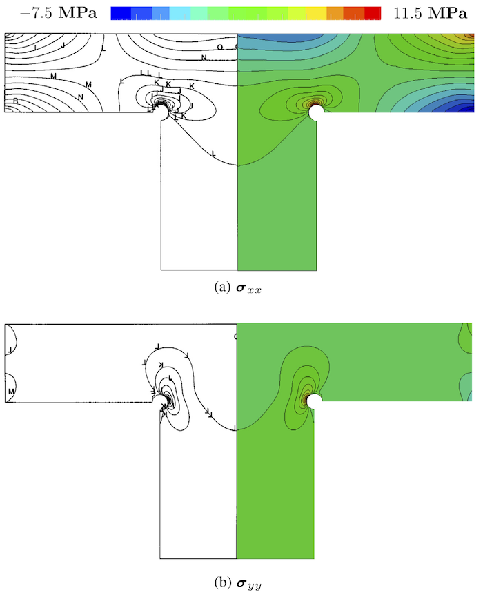
Figure 3: Predicted stress component distributions on the plane z = 0:0 m (right) compared with results from Demirdzic et al. (left).
The wall-clock times and memory requirements for each run are given in Table 1, where the results for the unsCoupled and segregated variants are compared. The unsCoupled solver used a bi-conjugate gradient stabilised linear solver with ILU(0) preconditioner, while the segregated variant used an implicit segregated solve with the same convergence tolerance of \(1 \times 10^{-6}\). In this case, the unsCoupled variant is approximately four times faster than the segregated variant but requires about four times more memory.
The wall-clock times given in Table 1 were recorded in 2015 using one core of a2.4 GHz Intel Ivy Bridge CPU. Better performance can be expected using a newmachine.
Table 1: Wall-clock time (in s) and maximum memory usage (in MB).
| Mesh | unsCoupled | segregated | ||
|---|---|---|---|---|
| Time | Memory | Time | Memory | |
| 624 | 0.2 | 15 | 0.7 | 8 |
| 4 992 | 2 | 58 | 6 | 24 |
| 39 936 | 29 | 340 | 98 | 88 |
| 319 488 | 421 | 2 400 | 2 220 | 560 |
PETSc timing and memory data for the petscSnes variant have not yet beenadded. Based on the current setup, the PETSc results are expected to be closeto, or better than, the unsCoupled variant.
The coupledUnsLinearGeometryLinearElastic solid model currently does not runin parallel. For a coupled solid model that does run in parallel, use thevertexCentredLinGeomSolid solid model.