Contact between curved beams: curvedBeams
Prepared by Ivan Batistić
Tutorial Aims
- Demonstrate how to perform a solid analysis with large deformations and large sliding contact.
Case Overview
This example considers large sliding between two curved beams (Figure 1). The lower beam is fixed at both ends, whereas the upper beam has a prescribed horizontal displacement of \(u_x = 31.5\) mm at both ends. Both beams are modelled as elastoplastic with isotropic hardening using the following material properties: Young's modulus \(E = 689.56\) MPa, Poisson's ration \(\nu = 0.32\), initial yield strength \(\sigma_Y = 31\) MPa and linear hardening coefficient \(H^‘ = 261.2\) MPa. The problem is solved using \(63\) equal displacement increments. The frictional response is considered, and the coefficients of friction are set to \(\mu = 0.3\). The beams are discretised using 50 cells in the circumferential and 5 cells in the radial direction. The problem is solved using the plane strain assumption, neglecting inertial and body forces.
![Figure 1: Problem geometry (dimensions in mm) [1]](/tutorials/more-tutorials/solid-mechanics/elastoplasticity/images/curvedBeams-geometry.png)
Figure 1: Problem geometry (dimensions in mm) [1]
Expected Results
Due to its larger diameter, the lower beam exhibits greater plastic deformation during the sliding (Figure 2). Theic deformation is expected to be reduced as the coefficient of friction increases the amount of plasticity. Video 1 shows the evolution of the equivalent (von Mises) stress distribution.
Figures 3 and 4 compare the evolution of the horizontal and vertical total reaction force between solids4foam and results reported in the literature [2]. The resulting evolution of the reaction forces is smooth and matches well with results from the literature. Reported results in solids4foam are obtained using the updated Lagrangian formulation (nonLinearGeometryUpdatedLagrangian) and foam-extend-4.1.
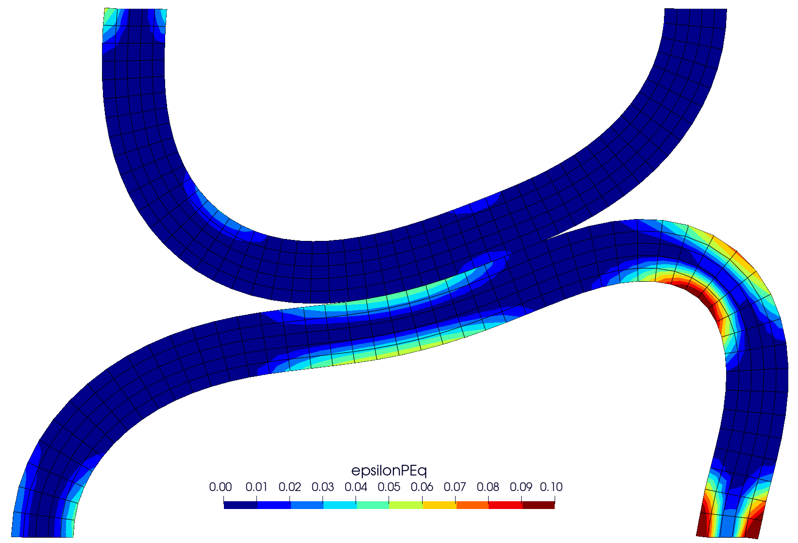
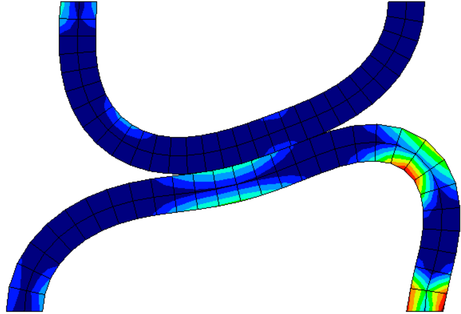
Figure 2 - Contours of equivalent plastic strain (epsilonPEq) at displacement of 15 mm (left), compared with solution from [2] (right)
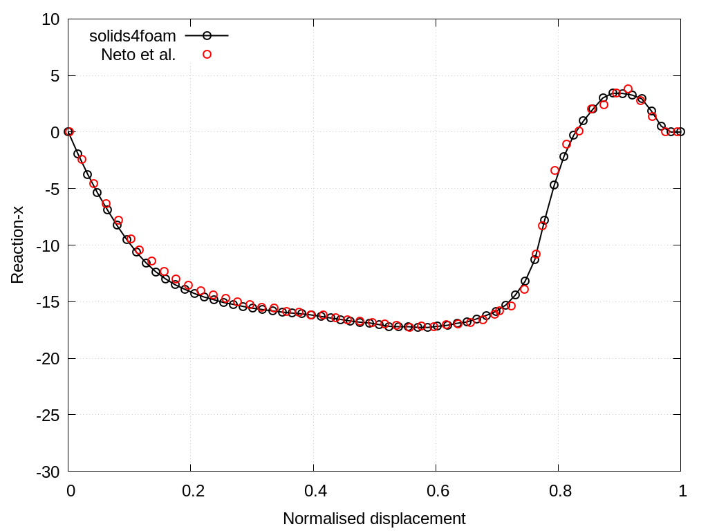
Figure 3 - Total reaction force in the x-direction
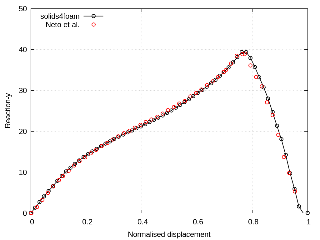
Figure 3 - Total reaction force in the y-direction
Video 1 - Evolution of the equivalent (von Mises) stress distribution
Running the Case
The tutorial case is located at solids4foam/tutorials/solids/elastoplasticity/curvedBeams. The case can be run using the included Allrun script, i.e. > ./Allrun. The Allrun script first creates the blockMeshDict file using the m4 scripting language from the blockMeshDict.m4 file located in system directory. Afterwards, blockMesh (> blockMesh) is used to create the mesh and the solids4foam solver is used to run the case (> solids4Foam). Optionally, if gnuplot is installed, the evolution of the horizontal and vertical reaction forces is plotted in the reaction-x.png and reaction-y.png files.
Verification and Convergence Study
The opt-in verification/ directory turns the curved-beams benchmark from solid-benchmarks/elastoPlasticity/curvedBeams into a mesh convergence study for this tutorial. It refines the tutorial blockMesh, extracts the total reaction force history on the fixed patch, and compares it with the published curves of Neto et al. [2] for friction coefficients of \(\mu = 0.0\), \(0.3\) and \(0.6\):
cd verification
./Allverify
On the finest 2 000-cell mesh the computed force history agrees with [2] to 2.3% RMS and 1.8% at the peak force, and the change in the history between successive meshes decreases monotonically with an observed order of 0.62. The study is separate from regressionTest.sh and is not run by the normal tutorial test suites. See the verification README for the mesh levels, options, and acceptance criteria.