Channel flow over a cavity with a flexible bottom: cavityFlexibleBottom
Prepared by Aaron Mullen-Hales, Philip Cardiff and Ivan Batistić
Tutorial Aims
- Demonstrates how to perform an internal-flow fluid-solid interaction simulation
Case Overview
This case involves a laminar flow of an incompressible fluid with a parabolic inlet velocity profile through a two-dimensional channel containing a flexible cavity in the bottom wall. The geometry of the fluid and solid domains is shown in Fig. 1. The channel height for all simulations is \(H = 1\,\mathrm{m}\). The fluid has a density of \(1\,\mathrm{kg/m^3}\) and a kinematic viscosity of \(0.01\,\mathrm{m^2/s}\). It enters the channel from the left-hand side with a parabolic velocity profile with a mean inlet velocity of \(1\,\mathrm{m/s}\), corresponding to a Reynolds number of \(Re = 100\) based on the channel height. A constant pressure is imposed at the outlet, and no-slip boundary conditions are applied at the channel walls. The flexible elastic plate forming the bottom of the cavity has a density of \(1000\,\mathrm{kg/m^3}\), a Young's modulus of \(500\,\mathrm{N/m^2}\), and a Poisson's ratio of \(\nu = 0.4\). Its deformation is described using the Saint Venant–Kirchhoff constitutive model. The case is solved as a transient problem until a steady-state solution is reached. A first-order Euler time discretisation scheme is used for both the fluid and solid solvers. To accelerate convergence to the steady state and suppress transient oscillations, additional damping is applied to the solid domain via the dampingCoeff parameter in constant/solid/solidProperties.
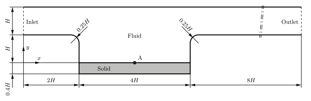 Figure 1: Geometry of the spatial computational domain for the channel flow over a cavity with a flexible bottom [1]
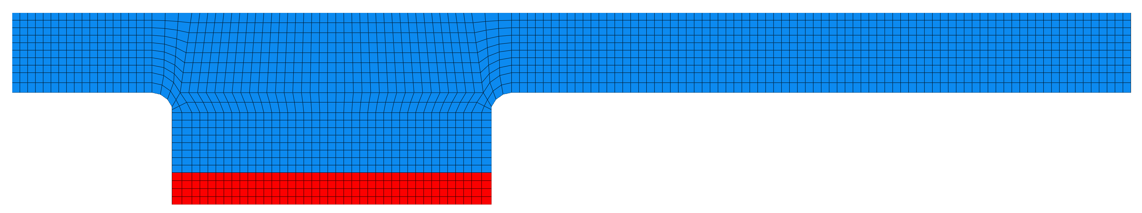 Figure 2: Computational domain discretisation: solid (red) and fluid (blue)
Running the case
The tutorial case is located at solids4foam/tutorials/fluidSolidInteraction/HronTurekFsi3. The case can be run using the included Allrun script, i.e. > ./Allrun. The Allrun script first executes blockMesh for both solid and fluid domains (> blockMesh -region fluid and > blockMesh -region solid ), and the solids4foam solver is used to run the case (> solids4Foam). Optionally, if gnuplot is installed, a file deflection.pdf will be created with the displacement history of point A, and a file force.pdf will be created with the history of the force on the interface.
Analysing Results
The vertical displacement of point A (located at \((4\,-1\,0)\)) is recorded in postProcessing/0/solidPointDisplacement_displacement.dat using a function object defined in system/controlDict. The forces acting on the fluid–solid interface are also recorded in postProcessing/fluid/forces/0/force.dat via the forces function object.
Figure 3 shows the convergence history of the vertical displacement of point A, while Fig. 4 presents the convergence of the interface force components. As can be observed, a steady-state solution is reached after approximately \(t = 120\,\mathrm{s}\).
Figure 5 shows the velocity field in the fluid domain together with the equivalent stress distribution in the solid domain. The results are in good agreement with those reported in [1] (see Fig. 6 therein). The results in [1] are obtained using a finer mesh, which explains the higher stress values observed near the plate corners due to stronger stress concentrations.
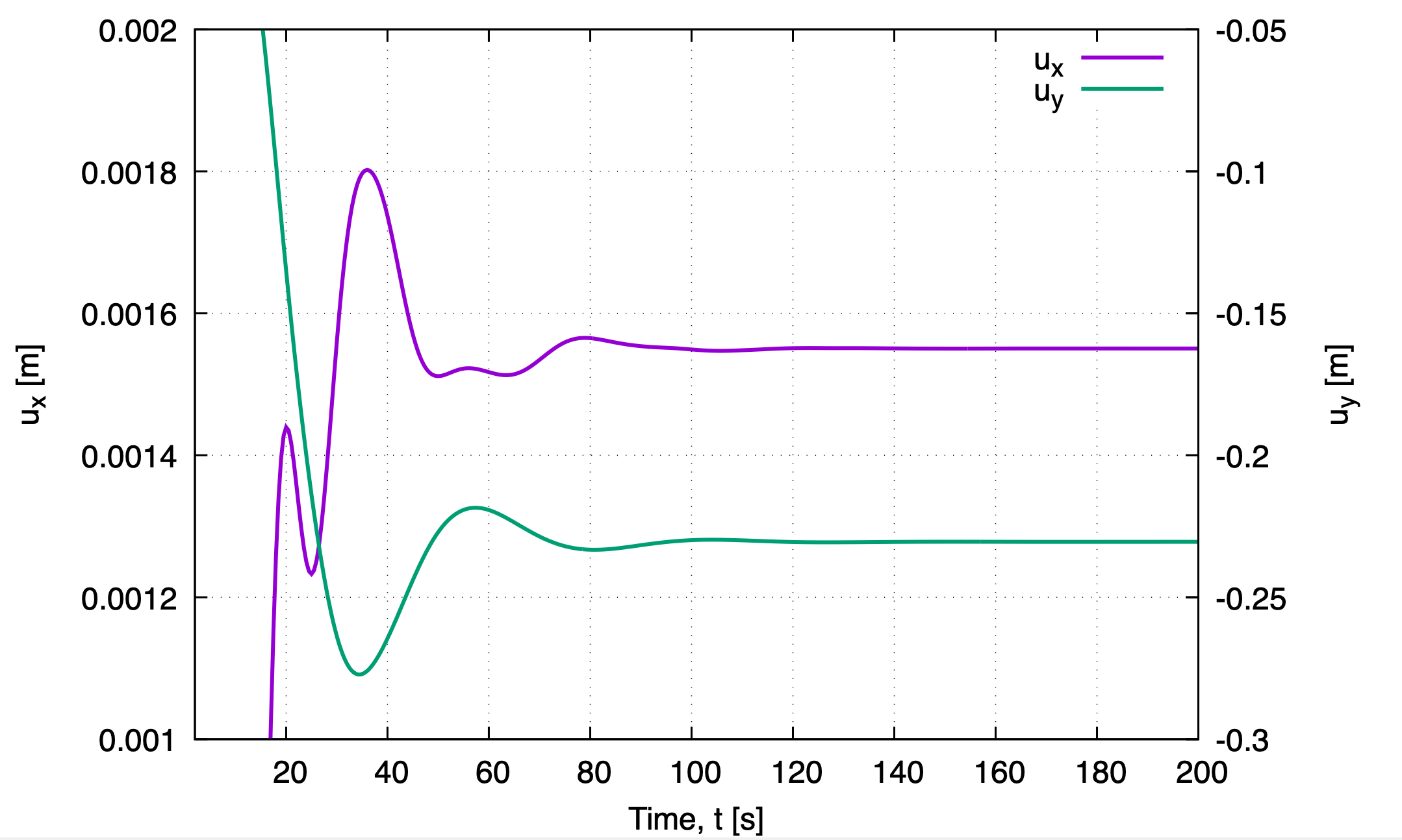 Figure 3: Convergence of the horizontal and vertical displacement of point A
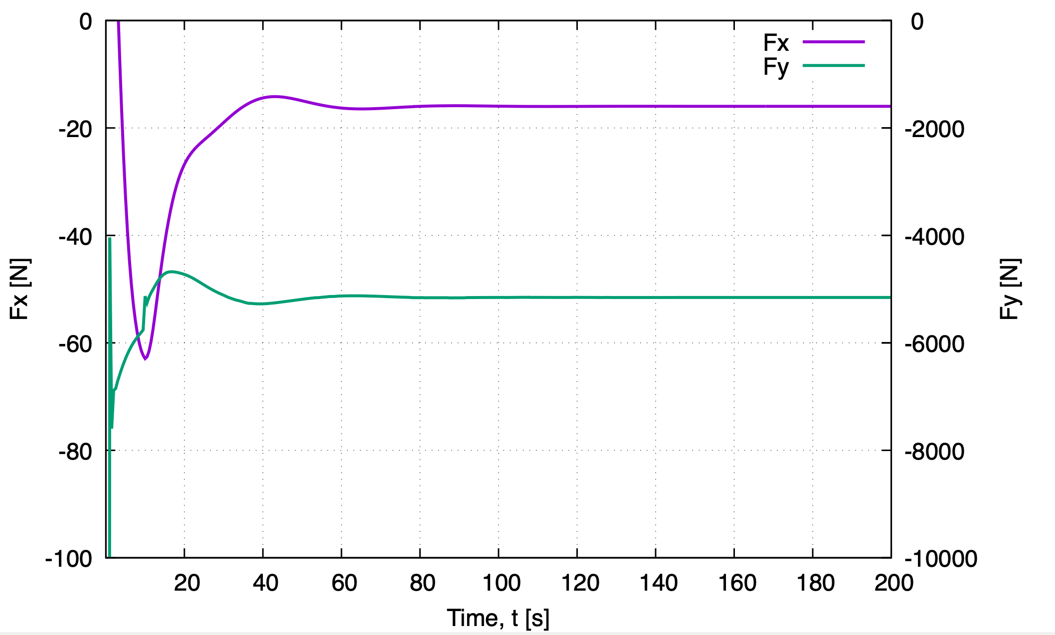 Figure 4: Convergence of the interface total force components
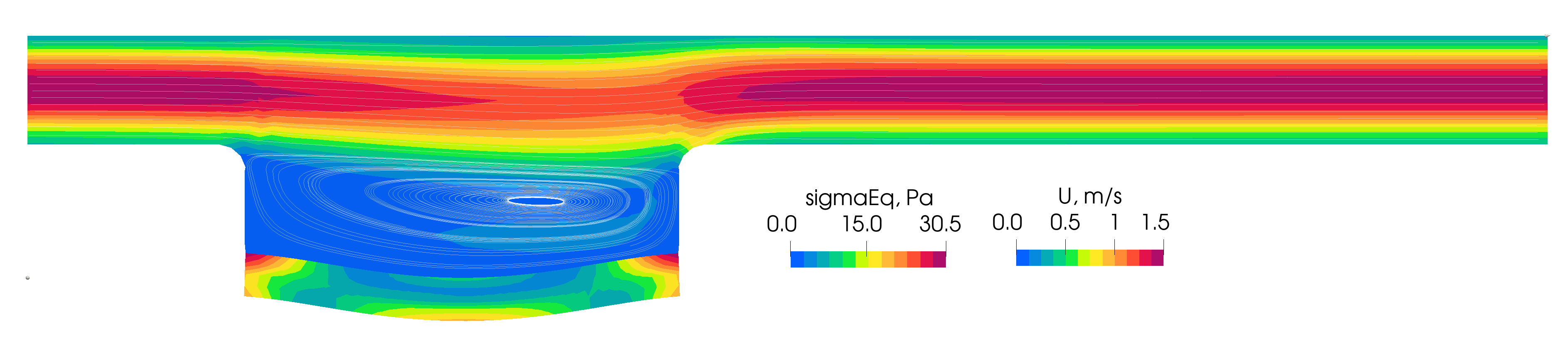 Figure 5: Velocity field in the fluid and equivalent stress in the solid part at the final time step
Results from the literature
The results reported by [1] show good agreement with those obtained using solids4foam. Figure 6 presents the velocity field and equivalent stress distributions reported in [1], while Fig. 7 shows the corresponding convergence histories of displacement and interface forces.
The interface force reported in [1] is several orders of magnitude smaller than that obtained in the present solids4foam simulation, which is explained by the different domain thickness used in the two studies.
For mesh with \(0.1\) m spacing, the vertical displacement reported in [1] is approximately \(-0.232\,\mathrm{m}\) (estimated from the published diagram), whereas the solids4foam prediction is \(-0.219\,\mathrm{m}\).
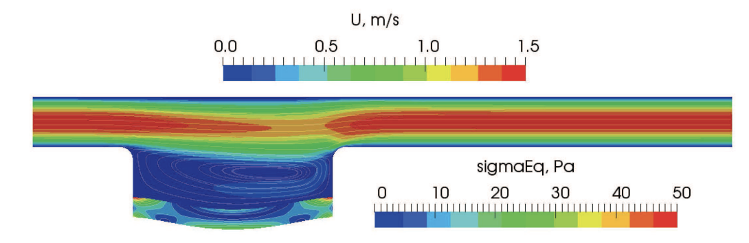
Figure 6: Velocity field in the fluid and equivalent stress in the solid part at the final time step, from [1]. Mesh spacing 0.025 m
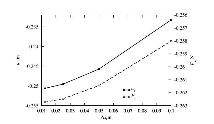 Figure 6: Displacement of point A and force at the plate as a funcion of cell size [1]