In-Plane Cantilever Subjected to an End Follower Load
Tutorial Aims
This tutorial demonstrates how to:
- simulate a geometrically nonlinear quasi-static beam problem
- apply a non-conservative circulatory follower force
- use pseudo-time to increment a static load
- compare free-end displacements with literature reference results
- perform a mesh sensitivity study
The case is the second benchmark presented in the beamFoam paper.
Prerequisites
- A compiled beamFoam installation
- A sourced, supported OpenFOAM.com environment
- gnuplot with the
pdfcairoterminal for generating the supplied plots - ParaView for visualising the deformed beam
Problem Description
A straight cantilever is clamped at its left end and subjected to a circulatory follower force at its right end. Unlike a force with a fixed global direction, the follower force rotates with the instantaneous end configuration. It is therefore configuration-dependent and non-conservative.
The load is increased linearly from zero to 134 kN over 1000 pseudo-time increments. Both time-derivative schemes are set to steadyState, so pseudo-time controls load incrementation rather than physical dynamics.
| Property | Value |
|---|---|
| Length | 100 m |
| Cross-section | circular |
| Radius | 0.65828153 m |
| Young's modulus | 2.3731844e8 Pa |
| Shear modulus | 1.1865922e8 Pa |
| Maximum follower force | 134 kN |
| Default mesh | 40 beam segments |
| Pseudo-time step | 0.001 |
| Number of load increments | 1000 |
The corresponding rigidities are approximately:
- flexural rigidity:
EI = 3.5e7 Nm^2 - shear rigidity:
GA = 1.61538e8 N
Case Setup
Beam Geometry and Nonlinear Controls
constant/beamProperties defines the circular beam and the nonlinear solution controls:
beams
(
    beam_0
    {
        crossSectionModel circle;

        circleCrossSectionModelDict
        {
            radius 0.65828153;
        }

        length      100;
        nSegments   40;
        E           2.3731844e8;
        G           1.1865922e8;
    }
);

beamModel coupledTotalLagNewtonRaphsonBeam;
The model uses:
nCorrectors 1000solutionTol 1e-10residualTol 1e-8
Boundary Conditions and Loading
The left patch is clamped:
0/W: zero fixed displacement0/Theta: zero fixed rotation
At the right patch:
0/WusesfollowerForceBeamDisplacementNR0/ThetausesmomentBeamRotationNRwith a zero applied moment
The follower force is read from constant/timeVsFollowerForce:
(
    (0 (0 0 0))
    (1 (0 0 1.34e5))
)
The force direction is updated as the free-end configuration changes. This boundary condition is the defining feature of the benchmark.
Quasi-Static Solution and Output
system/fvSchemes selects steadyState for both time-derivative schemes. system/controlDict advances from pseudo-time 0 to 1 with deltaT = 0.001.
The enabled function objects write:
- right-end displacement history
- left-end resultant force and moment history
- nonlinear convergence information
Running the Tutorial
From this tutorial directory:
./Allclean
./Allrun
The script creates the beam mesh, runs beamFoam and generates displacementPlot.pdf.
The principal output files are:
log.createBeamMeshlog.beamFoamdisplacementPlot.pdfpostProcessing/0/beamDisplacements_right.dat
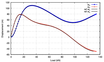
The default plot compares the calculated free-end displacement components against referenceResultsSimo.dat.
Post-Processing
To inspect the changing beam configuration:
touch case.foam
paraview case.foam
Apply Warp By Vector using pointW. Inspect multiple pseudo-time directories to see how the beam direction and follower-force direction evolve as the load increases.
The displacement history contains the free-end components. allPlots.gnuplot combines this history with AppliedLoad.dat to plot displacement against load.
Expected Results
The paper reports:
- good agreement with the Simo and Vu-Quoc reference solution
- approximately four to six Newton iterations per load increment
- closer agreement with the reference solution as the mesh is refined
- second-order spatial convergence of the final free-end displacement
The important validation quantities are the in-plane free-end displacement components w_x and w_z as the load increases to 134 kN.
Mesh Sensitivity Study
Run:
./runSweep.sh
The script runs meshes with 5, 10, 20 and 40 segments. It writes:
timing_summary.txt- displacement histories under
dispResults/ AppliedLoad.datdispComparison_Wx_MeshSizes.pdfdispComparison_Wz_MeshSizes.pdf
The script generates AppliedLoad.dat from the 20-segment displacement history and compares the mesh results with referenceResultsSimo.dat.
The sweep modifies nSegments in constant/beamProperties and leaves the last tested value, 40, in place.
The beamFoam paper additionally reports a convergence study using 10, 20, 40 and 80 control volumes. Extend the mesh_sizes list in runSweep.sh if the 80-segment result is required.
Troubleshooting
- If the force behaves as a fixed global load, confirm that
0/WusesfollowerForceBeamDisplacementNR, notforceBeamDisplacementNR. - If the load-displacement plot fails, confirm that
postProcessing/0/beamDisplacements_right.datexists and that gnuplot can findAppliedLoad.datandreferenceResultsSimo.dat. - If nonlinear convergence deteriorates near the final load, reduce
deltaTto use smaller load increments. - Run
./Allcleanbefore repeating the standard case after changing the mesh.
References
- Bali, S., Taran, A., Tuković, Ž., Pakrashi, V., and Cardiff, P. (2025). beamFoam: A Cell-Centred Finite Volume Solver for Nonlinear Geometrically-Exact Beams in OpenFOAM. OpenFOAM Journal, 5, 180-210.
- Argyris, J., et al. (1981). Nonlinear Finite Element Analysis of Elastic Systems under Nonconservative Loading: Natural Formulation. Part I: Quasistatic Problems.
- Simo, J. C., and Vu-Quoc, L. (1986). A Three-Dimensional Finite-Strain Rod Model. Part II: Computational Aspects. Computer Methods in Applied Mechanics and Engineering, 58, 79-116.