Bearing capacity of strip footing: stripFooting
Prepared by Philip Cardiff, Ivan Batistić, and Tian Tang
Tutorial Aims
- Demonstrate the poro-elasto-plasticity soil model.
Case Overview
This case demonstrates elasto-plastic soil-pore-fluid coupling. Following Small et al. [1], the validation case considers a smooth, perfectly flexible, uniformly loaded, and permeable strip footing acting on a layer of soil resting on a smooth rigid base. The problem also assumes that there is no horizontal force on any vertical section. The original geometry is sketched in Figure 1, and the soil and pore-fluid properties are given in Table 1. A plane strain condition is considered and gravity is neglected.
The case was adapted, with modifications, from Tian Tang's minigeotechfoam cases [3].
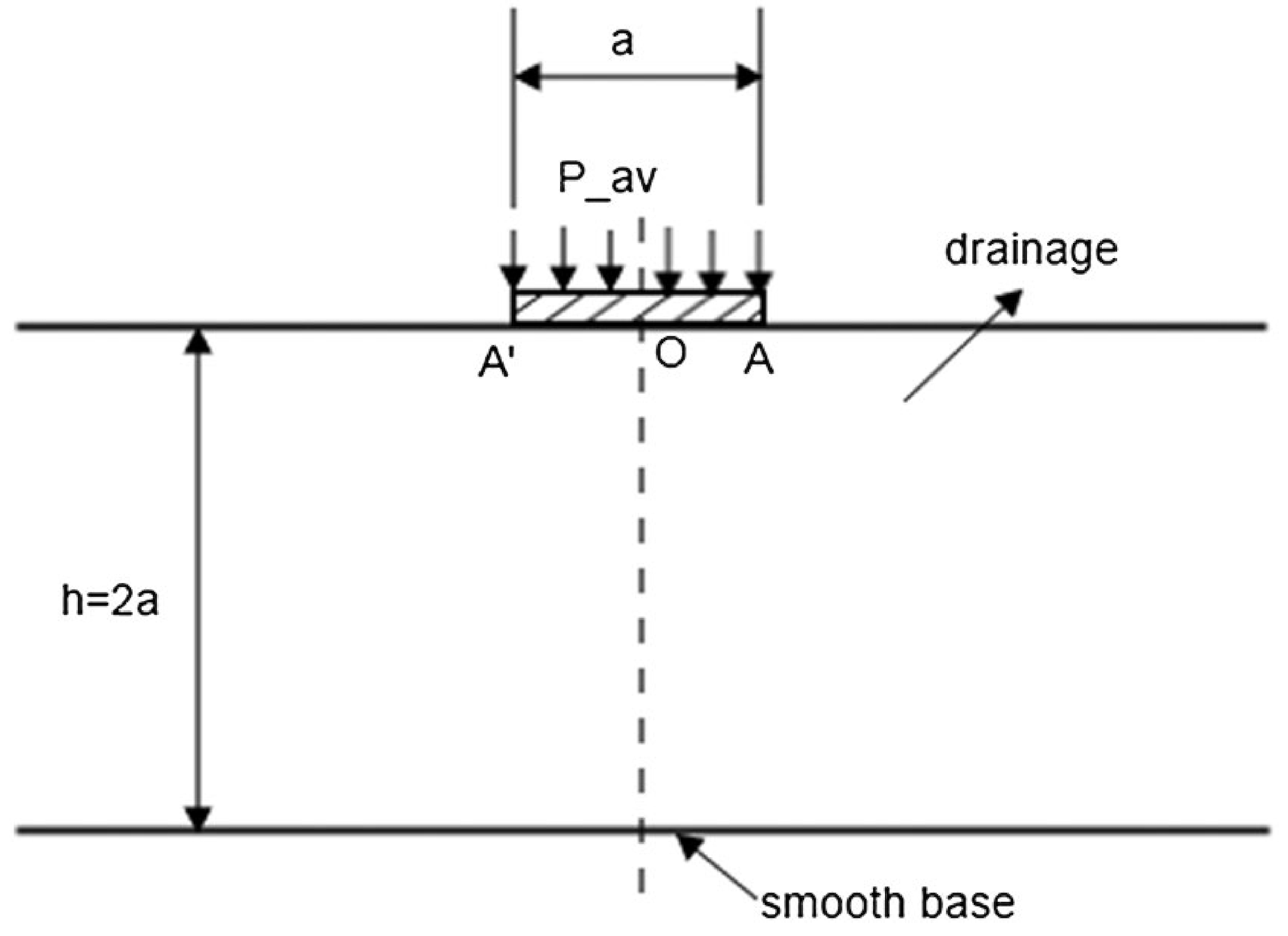
Figure 1 - Problem geometry [1,2]
Table 1 - Soil and pore-fluid properties reported in [1,2]
| Parameter | Symbol | Value |
|---|---|---|
| Young's modulus | \(E\) | \(2\cdot10^7\) Pa |
| Poisson's ratio | \(\nu\) | \(0.3\) |
| Hydraulic conductivity | \(k\) | \(0.001\) m/s |
| Porosity | \(n\) | \(0.3\) |
| Water specific weight | \(\gamma_w\) | \(1\cdot10^4\) N/m\(^3\) |
| Water bulk modulus | \(K_w\) | \(2.1\cdot10^9\) Pa |
| Degree of saturation | \(S_r\) | \(0.99\) |
| Friction angle | \(\phi\) | \(30^\circ\) |
| Dilation angle | \(\Psi\) | \(5^\circ\) |
| Cohesion | \(c\) | \(1\cdot10^5\) Pa |
The boundary conditions for the displacement field \(D\) and pore-fluid pressure field \(p\) are listed in Table 2.
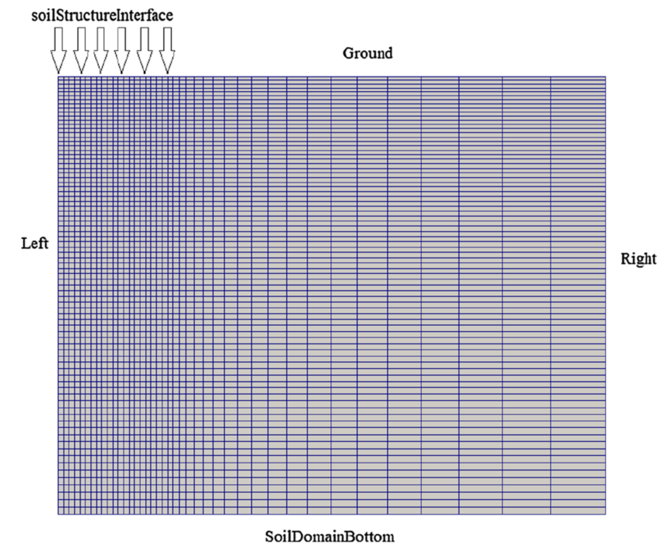
Figure 2 - Mesh and boundary conditions [2]
Table 2 - Boundary conditions for the displacement and pressure
| Boundary | \(D\) | \(p\) |
|---|---|---|
soilStructureInterface | solidTraction | fixedValue |
right | symmetry | symmetry |
left | solidTraction | zeroGradient |
ground | solidTraction | fixedValue |
soilDomainBottom | fixedDisplacementZeroShear | zeroGradient |
The soilStructureInterface displacement condition applies the time-varying load, the solidTraction conditions on left and ground are zero-traction conditions, and the fixedValue pressure conditions use \(p=0\).
Initially, there is no stress and no pore pressure in the domain. The load-rate parameter \(\omega\) is adopted from [1]:
\[\omega = \frac{d(P/c)}{d(T_v)}, \qquad T_v = \frac{c_vt}{a^2}.\]Here, \(P/c\) is the external pressure normalized by the soil cohesion, \(T_v\) is the dimensionless time, \(c_v\) is the one-dimensional consolidation coefficient, and \(a\) is the strip-footing width.
Note: some current case properties differ from the values reported in Table 1. In the dictionaries, the porosity is \(0.2\), the water bulk modulus is \(2.0\cdot10^9\) Pa, and the dilation angle is \(0^\circ\). Note also that the current mesh uses a uniform cell size.
Expected Results
In general, a smaller value of \(\omega\) corresponds to a slower load rate. Small et al. [1] suggested that \(\omega \leq 0.143\) represents a drained condition and \(\omega \geq 143\) represents a fully undrained condition. The intermediate values \(\omega = 1.43\) and \(\omega = 14.3\) represent slow and fast load rates in partially drained conditions, respectively. Tang et al. [2] provide a detailed comparison with Abaqus and the results from Small et al. [1].
Figures 3 and 4 show the pore-pressure distributions along the footing center line at different load levels for the slow load rate \(\omega = 1.43\) and the fast load rate \(\omega = 14.3\). The labels beside the curves indicate the normalized load level \(P/c\). At low load levels, the soil domain behaves elastically. At higher load levels, the soil reaches failure. The simulations show that excess pore pressure dissipates rapidly once plastic deformation occurs and dilation develops. This demonstrates the solver's ability to capture the interaction between pore-pressure development and nonlinear soil behaviour.
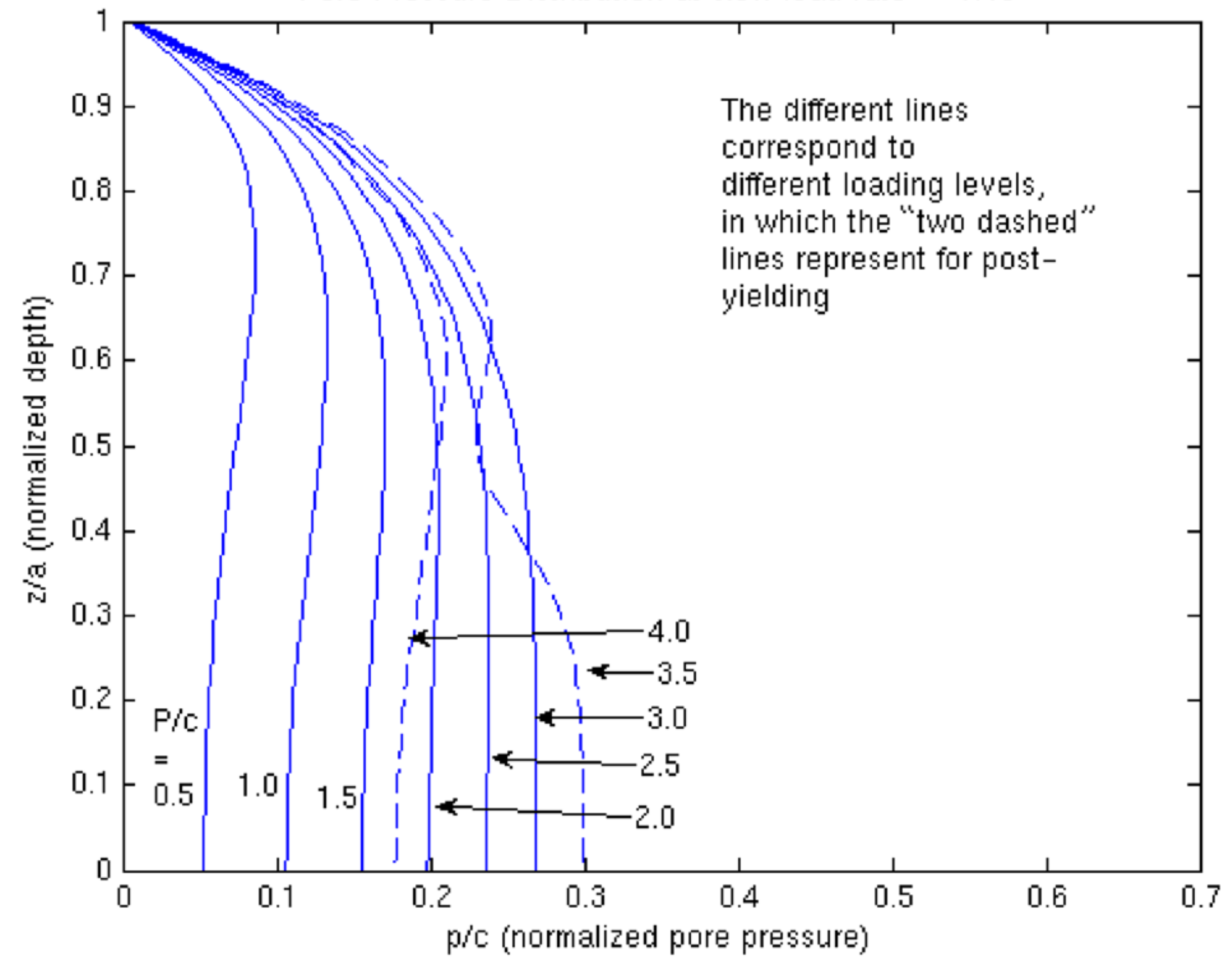
Figure 3 - Pore-pressure distribution at slow load rate \(\omega = 1.43\) [2]
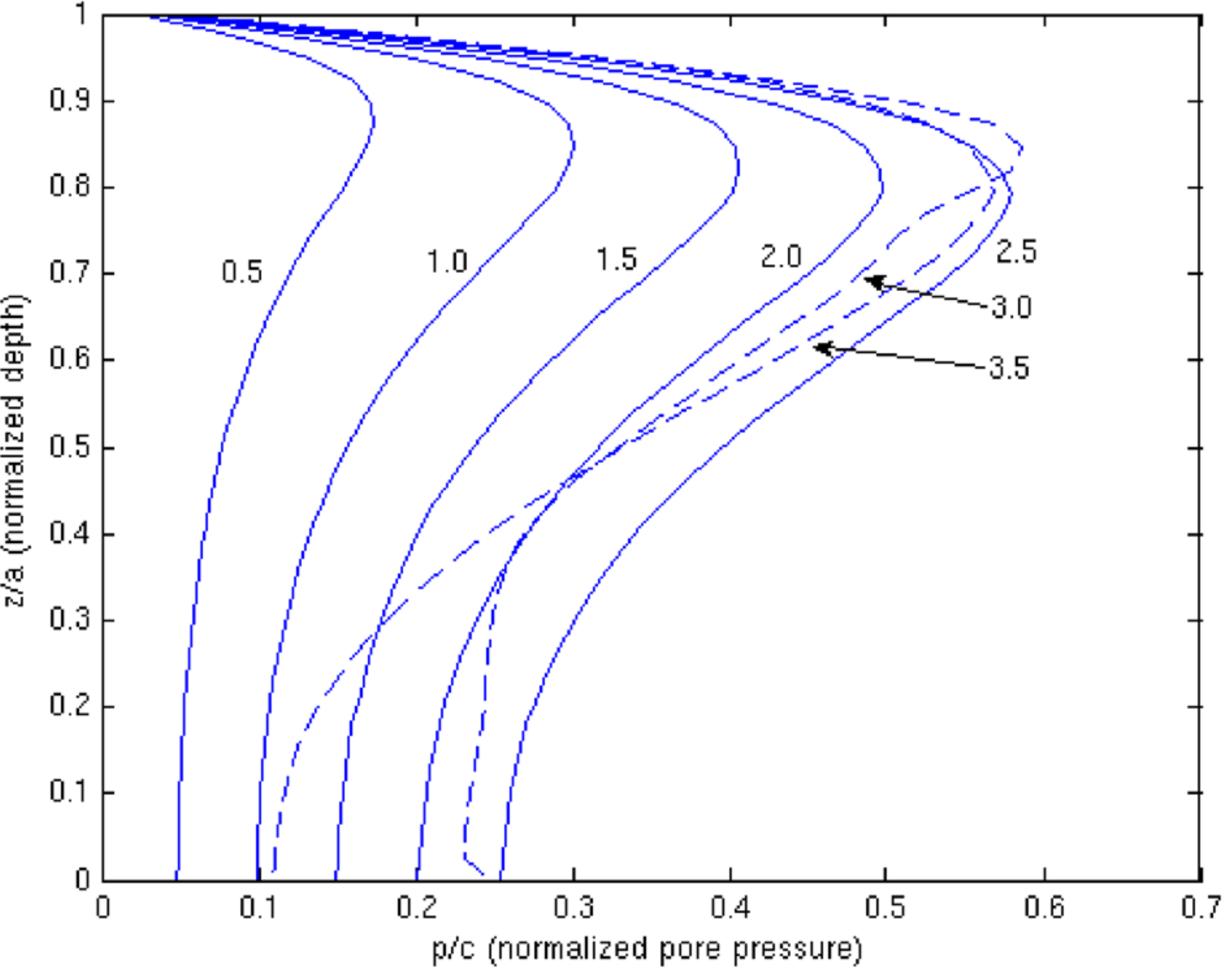
Figure 4 - Pore-pressure distribution at fast load rate \(\omega = 14.3\) [2]
Running the Case
The tutorial case is located at solids4foam/tutorials/solids/elastoplasticity/stripFooting. The case can be run using the included Allrun script, i.e. > ./Allrun.
The Allrun script first creates the mesh using blockMesh and runs the solids4Foam solver.